
Views: 0 Author: Site Editor Publish Time: 2026-07-17 Origin: Site


Automation engineers face a critical transition today. We are rapidly moving from traditional rotary-to-linear actuators, like ball screws, toward advanced direct-drive technology. This shift directly answers the relentless industry demand for shrinking cycle times and significantly tighter manufacturing tolerances. However, getting this mechanical transition right matters immensely. Over-specifying your direct-drive system drives up capital expenditure needlessly and wastes valuable machine footprint. Conversely, under-specifying your hardware leads to catastrophic thermal failures and guarantees you will miss your throughput targets. This guide provides a step-by-step engineering and business evaluation framework. It helps you select a permanent magnet linear motor that aligns perfectly with your specific automation requirements. You will learn how to balance dynamic force profiles, navigate complex topology choices, and evaluate vendor capabilities effectively.
Before examining detailed electromagnetic specifications, you must define your underlying business problem. Engineers often jump straight to force calculations without establishing the core project goals. You should first identify the primary driver behind your automation upgrade. Are you designing a high-speed packaging machine requiring massive throughput? Do you need nanometer-level precision for a semiconductor wafer inspection tool? Perhaps your facility simply wants to drastically reduce maintenance downtime. Establish these overarching parameters early to guide your technical decisions.
Legacy mechanical systems often fail to meet modern production demands. Traditional setups rely on rotary motors paired to belts or ball screws. These mechanisms inherently introduce mechanical backlash. They suffer from elasticity and mechanical wind-up during rapid acceleration profiles. Bearings, couplings, and belts wear down continuously over millions of cycles. By adopting linear motors, you eliminate these problematic mechanical intermediaries entirely. Direct-drive technology couples the payload directly to the moving magnetic field. You achieve zero mechanical backlash and remove physical wear components from the primary drivetrain.
You must establish hard system-level constraints before drafting a CAD model. Map out your available Z-height limitations meticulously. Direct-drive components often require different spatial volumes than slim ball screws. Moving mass restrictions also dictate your design limits. Heavy payloads lower the system's natural frequency and heavily complicate drive tuning. Furthermore, evaluate your environmental hazards. Cleanroom applications demand strict particle generation limits. Heavy machining environments expose components to coolant and conductive dust, necessitating robust sealing strategies.
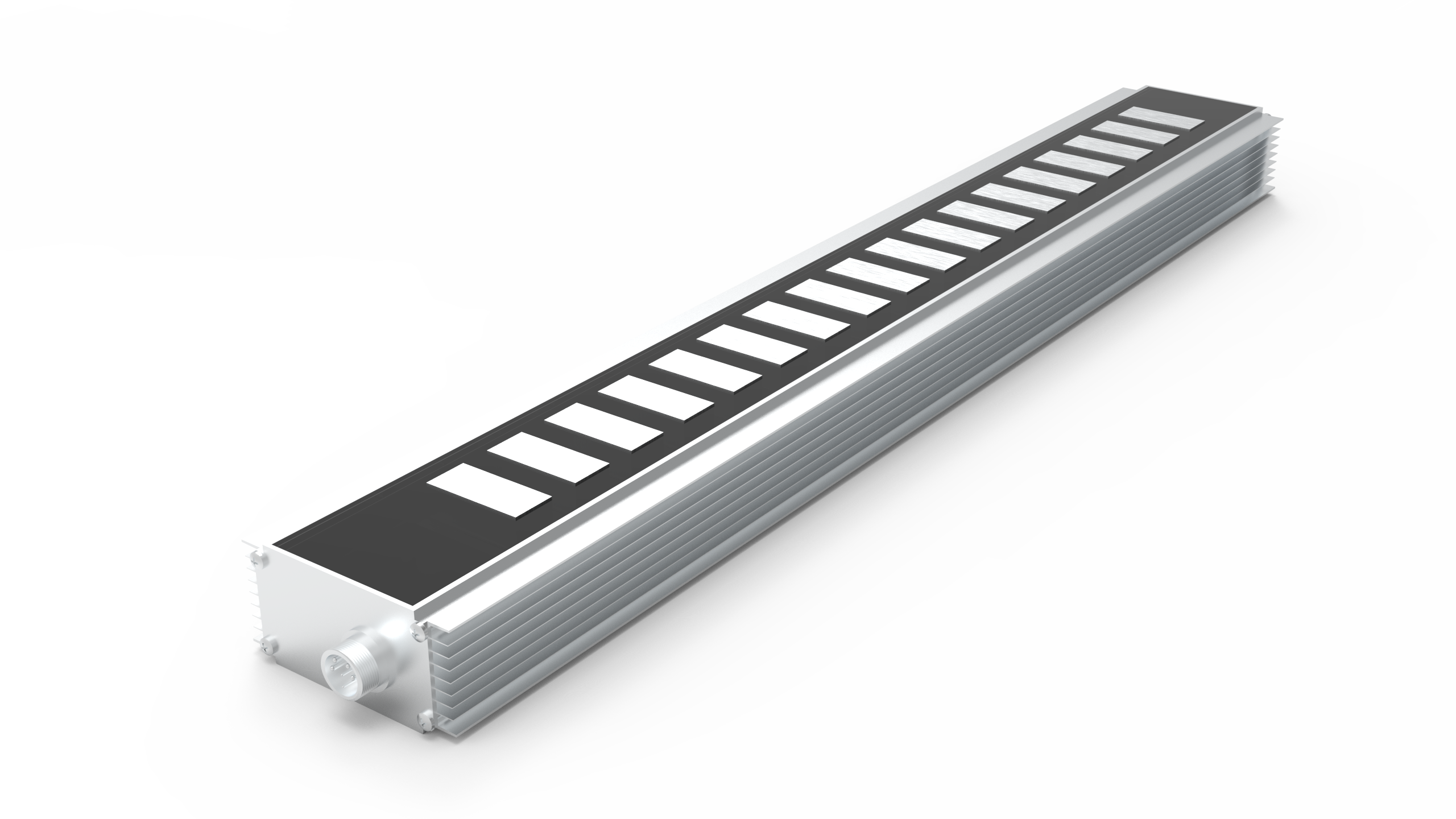
Accurate sizing dictates long-term machine reliability. You must understand the vast difference between Continuous Force (Fc) and Peak Force (Fp). The most critical sizing step involves calculating your exact motion profile. You need to map out the acceleration phase, constant velocity phase, deceleration phase, and dwell time. This mathematical map allows you to determine the Root Mean Square (RMS) continuous force. The RMS calculation guarantees the motor can sustain continuous, repetitive operation without exceeding its maximum thermal thresholds.
Many junior engineers commit a critical error during specification. They rely solely on Peak Force metrics to size their application. Peak Force represents the maximum electrical current the coils can handle before rapid thermal destruction occurs. The motor can only sustain this immense output for mere fractions of a second. Relying on peak ratings for continuous motion profiles guarantees rapid thermal faults and catastrophic hardware failure.
High-speed positioning requires careful attention to velocity, acceleration, and duty cycle. To optimize dynamic response, you should actively minimize the mass of the primary part, known as the forcer. A lighter moving mass dramatically reduces the required acceleration force. This reduction lowers overall heat generation and improves settling times at the end of a rapid move.
Precision capabilities rely entirely on your selected feedback loop. The direct-drive system cannot position itself blindly. It depends absolutely on the linear encoder. Resolution requirements strictly dictate your encoder selection. Optical encoders deliver nanometer-level resolution, making them ideal for metrology systems. However, they remain highly sensitive to ambient dust and machine vibration. Magnetic encoders offer immense durability for harsh environments, though they typically provide micrometer-level resolution.
Selecting the appropriate electromagnetic topology determines your baseline machine performance. This choice fundamentally dictates cogging torque severity, continuous force capacity, and thermal management strategies. You essentially choose between two dominant architectural styles.
These motors utilize copper coils wound directly around laminated silicon steel cores. The entire primary assembly interacts with a single, flat permanent magnet track.
These designs feature epoxy-potted coils moving suspended between two facing permanent magnet tracks arranged in a U-shape. The primary mover contains absolutely no iron.
Performance Comparison
| Feature | Ironcore Topology | Ironless Topology |
|---|---|---|
| Force Density | Very High | Moderate |
| Cogging Torque | Present (Requires compensation) | Zero (Inherently smooth) |
| Attractive Force | Very High (Requires robust bearings) | Zero |
| Thermal Dissipation | Excellent (Iron acts as heat sink) | Poor (Heat trapped in epoxy) |
| Moving Mass | Heavy | Light |
Implementing direct-drive hardware introduces unique physical challenges on the factory floor. Thermal degradation stands out as the most severe operational risk. High-performance direct-drive systems rely heavily on Neodymium magnets. These rare-earth magnets remain highly vulnerable to elevated temperatures. Pushing magnets past their safe operating limit causes irreversible demagnetization. You must execute precise cooling strategies early in the design phase. Natural convection suffices for low-duty operations. Forced air cooling pushes continuous force boundaries further. Liquid cooling circuits maximize sustained output, but they drastically increase the system footprint and plumbing complexity.
Servo tuning presents another harsh reality during machine commissioning. Standard rotary systems use gearboxes to mask load inertia mismatches. Direct-drive systems lack this mechanical reduction. The motor feels every ounce of load inertia directly. Servo drives must manage these aggressive mismatches instantly. Tuning requires injecting notch filters and managing complex Bode plots. You must verify your servo drive has the processing bandwidth to handle these raw, unmitigated loads.
Do not ignore cable management. High-flex cable tracks frequently represent the first catastrophic failure point in high-speed applications. Engineers often underestimate the physical stress applied to cables moving at five meters per second. You must strictly adhere to minimum bend radius specifications provided by cable manufacturers. Additionally, the mass of the moving cables must factor into your dynamic acceleration calculations.
Safety and compliance demand strict attention. Upon sudden power loss, the motor loses all electromagnetic holding force. Vertical applications require immediate drop prevention. You must install pneumatic counterbalance cylinders or active magnetic springs. Always integrate fail-safe mechanical brakes to secure the payload. Verify all components carry necessary CE, UL, and RoHS certifications to ensure global compliance.
Purchasing direct-drive technology requires evaluating hidden integration obstacles. You face a foundational choice between sourcing raw components or buying a fully integrated stage. Designing a custom stage involves procuring aluminum extrusions, linear rails, optical encoders, and motor coils separately. This route demands hundreds of mechanical engineering hours. Purchasing a pre-assembled linear stage shifts the alignment and integration burden back to the manufacturer. It dramatically reduces your engineering overhead and time-to-market.
Evaluate the vendor's engineering software rigorously. A reputable manufacturer provides empirical, proprietary sizing software. This software should simulate thermal behavior dynamically based on your imported motion profile. It must model thermal time constants accurately. Relying on static PDF datasheets for dynamic thermal sizing often leads to system failure.
Use a structured shortlisting logic to evaluate potential partners:
As a practical next step, gather your definitive motion parameters. Document your maximum payload mass, precise stroke length, and aggressive move times. Bring this strict data set to your shortlisted vendors to initiate a formal proof-of-concept discussion.
Choosing the correct direct-drive actuator remains an exercise in strict engineering balance. You must carefully weigh raw force density against nanometer precision and unavoidable thermal constraints. Successful adoption requires treating the motor, servo drive, encoder, and mechanical guides as a single, interdependent ecosystem. Isolating these components during the design phase invites system instability and failure.
Take action today to secure your project parameters. Download a comprehensive sizing checklist to organize your load requirements. Utilize a vendor's proprietary online motor selection tool to model your exact motion profile accurately. Contact a specialized application engineer immediately with your cycle time data to begin conceptualizing your optimal direct-drive solution.
A: Most modern direct-drive linear motors used in high-precision automation are actually synchronous AC permanent magnet motors. The terminology often overlaps. "Linear motor" describes the flat, unrolled physical structure. "Permanent magnet" specifies the secondary track type. They run on alternating current (AC) provided by a servo drive to electronically commutate the primary coils.
A: You can address cogging torque through both hardware and software. Hardware solutions involve skewing the magnets on the secondary track to smooth the magnetic transition. Software solutions utilize advanced servo drive algorithms. These modern drives map the specific force ripple and inject predictive counter-currents to cancel out the cogging effect dynamically.
A: Yes, but they require critical safety considerations. Because these motors lack mechanical friction, losing power means the payload will immediately drop. You must integrate pneumatic or magnetic counterbalance systems to offset gravity. Additionally, install fail-safe mechanical brakes to secure the payload during unexpected power losses or emergency stops.
A: Overheating causes irreversible demagnetization of the permanent magnets. Once demagnetized, the motor loses its ability to generate the specified force, permanently ruining the hardware. To prevent this, always integrate thermistors or PTC sensors directly into the coil assembly. These sensors provide critical drive-level protection by cutting power before thermal limits are breached.


 English