
Views: 0 Author: Site Editor Publish Time: 2026-07-16 Origin: Site


Specifying a motorized roller demands precise mechanical engineering. You must balance aggressive throughput targets against harsh physical load realities. Missing this delicate balance creates severe operational risks. Over-specifying your components inflates capital expenditure needlessly. You waste valuable budget on unused power. Conversely, under-specifying leads to rapid thermal failure. You face premature gear wear and costly system downtime. Facility managers combat this specification challenge daily. You need a reliable technical framework to navigate these choices. This article serves as your comprehensive technical evaluation guide. We will analyze how internal design factors dictate strict performance boundaries. You will learn to evaluate complex speed, torque, and thermal metrics. We will also explore advanced gear reductions and motor core technologies. Armed with this robust data, you can confidently engineer modern material handling systems.
Electric motor design relies on strict mechanical physics. Speed and torque share a direct inverse relationship. As rotational speed increases, available driving force decreases proportionally. You cannot maximize both variables simultaneously in a single compact unit. This limitation dictates every system design choice you make.
Engineers must read manufacturer performance curves accurately. A typical curve maps rotational speed directly against torque output. You will notice two distinct operating zones on these graphs. The nominal zone represents safe, continuous daily operation. The peak zone shows heavy load conditions. Operating in the peak zone causes heat to accumulate rapidly. Prolonged exposure here triggers complete motor stall.
Prioritizing maximum speed impacts material handling capabilities severely. Specifying hardware for high transport speeds limits your available acceleration torque. This deficit makes accelerating heavy industrial loads incredibly difficult. Static loads might not even overcome initial inertia. Motor stalling becomes a frequent operational headache for maintenance teams. Packages pile up and throughput drops drastically.
Buyers must fundamentally change their evaluation lens. Do not just specify steady-state transport speeds based on average loads. Instead, rigidly define your absolute worst-case scenario. Identify steep incline starting zones. Measure maximum pallet weights in dense accumulation zones. Assess friction coefficients on specialized belting materials. These demanding physical scenarios dictate your true mechanical torque requirements. Designing for the worst case ensures uninterrupted daily operation.
Manufacturers build internal drives using two primary core technologies. You will encounter standard brushed DC motors frequently. You will also see advanced Brushless DC (BLDC) motors. Both serve distinct material handling needs across modern facilities.
BLDC designs deliver superior electrical-to-mechanical power conversion. They eliminate physical friction entirely. They do this by removing traditional carbon brushes. Magnets and electronic controllers handle the rotational switching instead. This modern design choice directly improves overall energy efficiency. It also vastly improves internal heat dissipation. Better cooling allows for much longer continuous runtimes. Busy facilities rely heavily on this extended uptime.
Torque delivery also differs dramatically between the two technologies. BLDC designs offer a remarkably flatter performance curve. They provide highly consistent torque across widely varying speed ranges. Brushed counterparts often experience sharp torque drop-offs at higher speeds. This drop-off causes sluggish performance during high-speed sorting operations.
Your decision framework must weigh these operational benefits carefully. BLDC units require a substantially higher initial financial investment. They also mandate compatible electronic driver cards for precise control. However, their superior longevity makes them ideal for demanding environments. Facilities running complex continuous-duty cycles benefit greatly from this architecture. You avoid the regular maintenance required by wearing carbon brushes.
| Core Feature | Brushed DC Core | Brushless DC (BLDC) Core |
|---|---|---|
| Internal Friction | High (Requires Physical Brushes) | Low (Magnetic Operation) |
| Thermal Efficiency | Moderate Heat Dissipation | Excellent Heat Dissipation |
| Torque Delivery | Variable at High Speeds | Flat and Highly Consistent |
| Maintenance Needs | High (Brush Replacement) | Minimal (Solid State) |
| Ideal Application | Light Duty / Intermittent Cycles | Continuous / High Throughput |
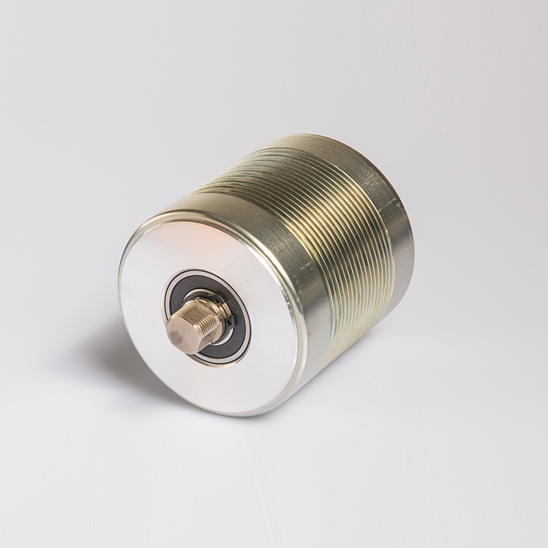
Integrating gearboxes directly inside the roller tube is standard industry practice. These mechanical reducers translate raw motor RPM into usable force. High-speed motor spinning alone cannot move heavy cardboard boxes. The internal transmission bridges this fundamental physical gap. It converts rapid rotation into heavy pushing power.
Most premium designs utilize planetary gear reducers. Planetary configurations offer incredible engineering advantages. They maintain a very compact physical size. They distribute physical loads evenly across multiple satellite gears. A central sun gear drives several surrounding planet gears. This intelligent arrangement handles high-speed mechanical inputs incredibly reliably. It resists shearing forces better than standard spur gears.
However, this internal transmission introduces an unavoidable efficiency tax. Every added gear stage creates additional internal friction. You typically lose five to ten percent mechanical efficiency per stage. Adding more stages multiplies your total torque output heavily. Unfortunately, it drains your overall electrical efficiency simultaneously. Power turns into excess heat instead of forward motion.
Specifying the correct gear ratio requires careful mathematical matching. High gear ratios multiply torque significantly. You need high ratios for heavy pallet handling applications. These heavy systems operate safely at lower surface speeds. Conversely, low gear ratios prioritize rapid RPM output. Choose low ratios strictly for lightweight package sorting operations.
Review these essential best practices during your specification phase:
Material handling lines rarely experience perfectly static conditions. Sudden load fluctuations pose a constant and hidden threat. Heavy items dropping onto a transport zone cause immediate physical shocks. These shocks trigger massive electrical current spikes inside the motor. Frequent stop-and-go accumulation actions demand repeated motor surges. These dynamic loads stress the entire electrical architecture daily.
High continuous torque demand drives up amperage draw predictably. Increased amperage directly generates high internal heat. The enclosed metallic tube struggles to release this thermal energy quickly. Operating high-amperage motorized rollers constantly risks severe internal overheating. The confined space traps heat against sensitive copper windings.
Built-in thermal protection features remain absolutely non-negotiable. Quality hardware includes internal thermal sensors or precise thermistors. These micro-sensors monitor winding temperatures constantly during operation. They trigger safety protocols before catastrophic winding failure occurs. The system safely shuts down the drive unit automatically. This prevents complete motor burnout and costly replacement procedures.
Facility engineers often face a critical implementation risk here. You must never specify units based solely on peak torque ratings. Continuous operation near peak load limits triggers rapid thermal faults. You will experience constant, frustrating line stoppages. Evaluate your exact duty cycle carefully. Intermittent use naturally allows the copper windings to cool. Continuous use demands strict adherence to much lower nominal load limits. Ignoring this principle guarantees frequent hardware failures.
Choosing the optimal drive requires a highly structured engineering approach. Guessing leads to expensive operational bottlenecks. Follow this proven step-by-step framework. It will narrow down your complex procurement choices effectively.
Designing an efficient conveyor line demands precise component matching. An optimized drive unit rarely features the absolute highest speed. It rarely features the absolute highest torque rating either. Instead, it represents the most efficient engineering intersection of both metrics. Your unique product load profile dictates this exact sweet spot. Finding it ensures smooth, uninterrupted daily operations.
Take these immediate action steps before finalizing any procurement decisions:
Do not rely solely on basic marketing catalog specifications. Consult directly with technical manufacturer engineering teams. Ask them to run advanced load simulations using your data. Verifying these complex thermal and mechanical limits ensures long-term operational success. Proper specification protects your capital investment and maintains throughput.
A: Continuous torque is the load the roller can move indefinitely without overheating, while peak torque is the maximum force available for short bursts (like starting a heavy load).
A: A larger diameter tube increases linear surface speed but reduces the effective torque applied to the load, assuming the internal motor output remains constant.
A: Low-speed operation often forces the motor to draw higher current to maintain torque, generating excess heat that the enclosed tube struggles to dissipate efficiently.
A: Yes, mechanically and electrically, but the efficiency gains are most noticeable in high-cycle or continuous-duty applications where heat reduction and longevity offset the higher initial cost.


 English