
Views: 0 Author: Site Editor Publish Time: 2026-07-18 Origin: Site


Modern engineering demands faster, more precise motion control. You need systems pushing boundaries without mechanical breakdown. Traditional rotary configurations rely heavily on ball screws, rack-and-pinion setups, or timing belts. These mechanical linkages naturally introduce friction, backlash, and long-term wear. The industry continues shifting toward direct-drive solutions to overcome these stubborn physical limitations. We see an increasing adoption of direct-drive linear topologies in high-end automation.
This transition helps engineers resolve complex throughput bottlenecks. We will compare traditional rotary architectures against direct-drive alternatives. You will learn how to evaluate critical performance metrics, thermal constraints, and integration requirements. Our objective comparison helps you specify the optimal motor type based on precision thresholds and load profiles. This guide empowers you to make confident engineering decisions for your next precision application design.
Traditional rotary motor architectures rely heavily on secondary mechanical linkages. Engineers typically use lead screws, timing belts, or gearboxes to convert rotary motion into linear motion. Every mechanical linkage introduces inherent physical limitations into your system. You introduce friction, mechanical elasticity, and microscopic wear every time gears mesh or belts stretch. These elements degrade system accuracy over time. They also require frequent maintenance to prevent catastrophic mechanical failure during production.
A direct-drive approach completely removes these secondary mechanical conversion components. You can visualize a permanent magnet linear motor as a traditional rotary motor sliced open and unrolled flat. The stator becomes the stationary magnet track. The rotor becomes the moving forcer coil. Electromagnetic force applies directly to the payload. You eliminate intermediate mechanical transmission entirely.
This structural difference solves a major engineering problem. Mechanical conversion acts as a severe bottleneck for throughput and accuracy. Advanced manufacturing and semiconductor inspection demand nanometer-level precision. Mechanical compliance in ball screws makes settling times unacceptably long. Direct-drive solutions eliminate this compliance. They allow machines to index faster, capture clearer inspection images, and significantly increase overall factory throughput.
Positioning accuracy and repeatability highlight the most distinct differences between these two technologies. Rotary systems are strictly limited by screw pitch accuracy and mechanical backlash. Even the highest precision ground ball screws suffer from thermal expansion during high-speed operation. This expansion shifts the mechanical pitch, destroying sub-micron repeatability. Conversely, linear direct-drive systems rely entirely on the resolution of the linear encoder and controller bandwidth. They routinely achieve true sub-micron precision because no mechanical linkages distort the position feedback loop.
Speed and acceleration profiles also diverge drastically. Engineers often cap rotary system speeds to avoid the critical speed threshold of ball screws. Pushing a screw beyond its critical speed causes whipping and severe vibration. Direct-drive architectures remain unrestricted by mechanical rotation limits. They routinely exceed 5 meters per second in velocity. Furthermore, they easily achieve 10 Gs of acceleration, enabling lightning-fast indexing movements.
Force and load handling characteristics favor traditional systems under specific conditions. Rotary architectures provide a superior mechanical advantage via gear reduction. They excel at moving massive, high-friction loads vertically or horizontally. Direct-drive architectures deliver incredibly high peak forces but typically offer lower continuous force density compared to geared setups. Engineers must carefully calculate root-mean-square (RMS) forces to prevent direct-drive coil overheating under continuous heavy loads.
Table: Performance Metrics Comparison
| Metric | Rotary Motor (Ball Screw) | Permanent Magnet Linear Motor |
|---|---|---|
| Positioning Accuracy | Limited by backlash and screw pitch | Limited only by encoder resolution |
| Maximum Velocity | Typically < 2 m/s (screw whip limit) | Regularly > 5 m/s |
| Acceleration | Low to Moderate (1-2 Gs) | Extremely High (> 10 Gs) |
| Continuous Force Density | High (leveraged by gear reduction) | Moderate (limited by direct coil heating) |
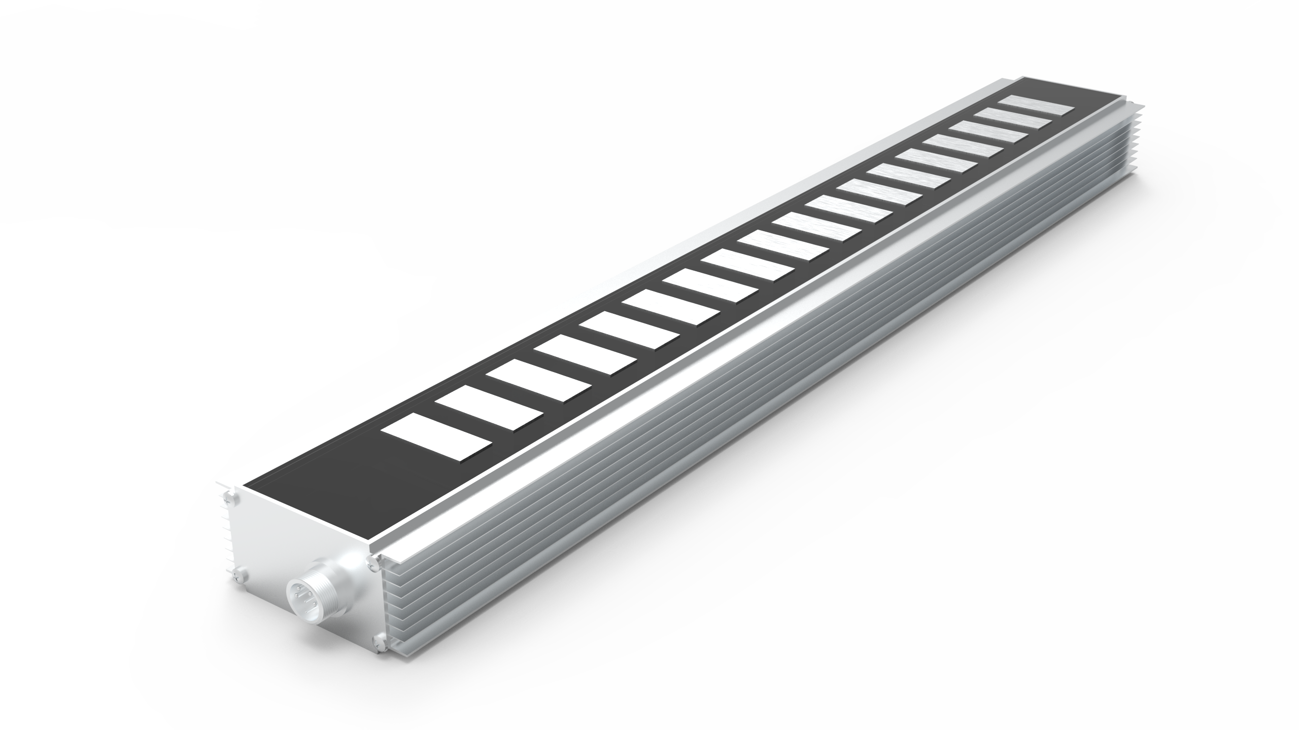
Direct-drive architectures introduce unique implementation challenges demanding careful engineering oversight. Thermal management remains a critical concern for precision applications. In a direct-drive setup, the forcer coil couples directly to the payload carriage. Heat transfers immediately into the application structure. This localized heating causes thermal expansion in precision tooling. Engineers mitigate this risk using forced air or dedicated liquid cooling plates mounted between the motor and the payload.
Assembly procedures require strict safety protocols. High attractive forces exist between the iron-core forcer and the stationary magnet track. These forces complicate installation significantly. Technicians face severe pinching hazards if they improperly handle these magnetic components during machine integration. You must utilize non-magnetic shims and specialized rigging tools when mating the coil to the track.
Engineers must also evaluate cogging torque and force ripple. Cogging torque occurs as the iron-core coil passes over individual magnetic poles. This creates a jerky motion profile at extremely low speeds. We classify direct-drive solutions into two main variants to address this:
System reliability heavily influences your final architectural decision. Traditional rotary systems utilize heavily commoditized components. While widely available, these components demand rigorous maintenance schedules. Lead screws and linear bearings require regular lubrication intervals. You must plan for periodic replacement of worn mechanical parts. This planned downtime disrupts 24/7 high-cycle production environments. Over looking lubrication schedules causes rapid system degradation.
Direct-drive configurations represent a fundamental shift in machine maintenance philosophy. Because these systems utilize true contactless motion, mechanical wear is virtually eliminated. The only contacting parts are the linear guide bearings supporting the payload. You avoid the rapid degradation typical of ball screws operating under heavy acceleration.
However, implementing contactless motion requires specialized component integration. linear motors demand high-precision optical or magnetic linear scales running the full length of travel. You also need rare-earth magnet tracks spanning the entire stroke. While these systems remain largely maintenance-free, their initial integration requires high precision. Properly installed direct-drive units deliver exceptional long-term reliability across thousands of operating hours without mechanical intervention.
Understanding form factor sub-categorization helps you shortlist the exact hardware for your specific use case. The market primarily offers flat architectures and tubular architectures. Each serves a distinct operational purpose.
Flat or U-channel architectures dominate ultra-high-precision sectors. The ironless U-channel design eliminates attractive forces between the coil and the track. This structural choice reduces bearing load and eliminates force ripple entirely. You should specify this form factor for extreme precision, low-mass payloads, and applications requiring perfect velocity stability. Semiconductor lithography and optical inspection machines almost exclusively utilize flat ironless designs.
Tubular linear shaft architectures provide a completely different value proposition. These models enclose the rare-earth magnets inside a stainless steel tube. The forcer coil wraps completely around this shaft. This design inherently cancels out extreme radial attractive forces, making assembly much safer. Tubular models serve as excellent drop-in replacements for traditional pneumatic cylinders. Furthermore, they are inherently easier to seal against environmental contaminants. Many tubular variants achieve IP67 or IP69K washdown compliance. This makes them ideal for food processing, packaging, and harsh industrial environments where flat magnetic tracks would attract destructive ferrous debris.
Choosing between rotary and direct-drive motion boils down to aligning physics against your specific application requirements. No single technology acts as a universal solution. You must evaluate your load, precision threshold, and environmental constraints. Use the following guidelines to inform your specification process.
The choice between mechanical transmission and direct drive is rarely about which technology is universally better. It requires meticulously matching motor physics to your application’s tolerance for backlash, required throughput, and environmental constraints. Traditional setups continue dominating high-torque, heavy-lift applications. However, direct-drive architectures unlock unparalleled speed, sub-micron precision, and contact-free reliability for advanced automation tasks.
Your next step requires practical system evaluation. First, map out your exact motion profile, including peak acceleration and continuous RMS force. Next, request a thermal simulation based on your specific duty cycle to ensure safe operating temperatures. Finally, utilize a sizing calculator matrix to compare expected settling times between a ball screw and a direct-drive stage. Rigorous front-end simulation guarantees you specify the perfect architecture for your exact engineering challenge.
A: No. Because they are direct-drive and lack mechanical transmission components like gears or ball screws, backlash is inherently eliminated from the motion profile.
A: Not inherently. Unlike a lead screw which can self-lock via friction, linear motors will drop vertical loads upon power loss unless you integrate external pneumatic or magnetic brakes.
A: It depends on the specific design. Exposed flat magnet tracks can attract ferrous dust, causing rapid failure. For harsh environments, you must specify enclosed tubular architectures or systems utilizing IP-rated protective covers.


 English