
Views: 0 Author: Site Editor Publish Time: 2026-07-18 Origin: Site


Modern automation demands cycle times and precision levels that traditional mechanical transmissions struggle to sustain. Today, standard rotary systems face severe physical limits. They restrict maximum acceleration and introduce friction. They often hold back manufacturing efficiency in high-stakes environments. Essentially, a linear motor serves as an "unrolled" rotary motor. It provides direct-drive linear motion seamlessly. This design entirely eliminates belts, ball screws, and complex rack-and-pinion assemblies. The stator and rotor lay flat. They translate electromagnetic force directly into rapid movement. This structural shift brings unparalleled speed and smoothness.
We designed this article as a technical evaluation guide. You will learn the core structural differences. You will evaluate multiple architecture types. We will help you determine if the performance gains justify their integration complexities and upfront costs.
Mechanical engineers constantly battle physical friction. Rotary-to-linear conversion mechanisms inherently restrict performance. Standard components like ball screws and timing belts introduce compliance. They stretch and bend under heavy dynamic loads. They also experience ongoing mechanical wear over thousands of cycles. Over time, these parts degrade significantly. You will notice increased hysteresis during operation. Repeatability drops as bearings wear down. Mechanical linkages create physical speed bottlenecks. These physical limits prevent automation equipment from scaling production rates safely. Moving parts generate heat and vibration. Eventually, they fail and halt production completely.
A traditional rotary motor requires gearboxes. You must couple the motor to a screw. The screw must turn to drive a nut forward. This entire sequence wastes energy. It introduces multiple points of failure. Every coupling adds a tiny bit of error. Engineers call this error backlash. When the motor reverses direction, the nut hesitates. This hesitation destroys precision in micromachining tasks. Direct drive eliminates these intermediary steps completely.
A direct-drive approach changes everything. A linear motors system shifts the mechanical paradigm entirely. Picture a standard rotary motor unrolled and laid perfectly flat. The traditional circular stator becomes a stationary magnetic track. The rotating component transforms into a moving coil. We call this moving coil the forcer. The electromagnetic flux travels directly across a precisely maintained air gap. This gap separates the moving coil from the stationary magnets. Because nothing touches, nothing grinds together. We remove mechanical intermediaries entirely from the drive train. Electrical power converts directly into translational movement. You do not need to worry about rotary inertia matching. The mass of the payload becomes the primary mechanical concern. This simplifies tuning the servo control loops. Engineers can push the system harder.
Removing mechanical elasticity transforms system responsiveness. Direct-drive configurations deliver significantly higher dynamic stiffness. You get immediate response times without any backlash. Acceleration profiles steepen dramatically compared to screw drives. The machine follows control commands exactly as programmed. This direct coupling ensures high-fidelity motion profiles. We define success in direct-drive automation through several criteria:
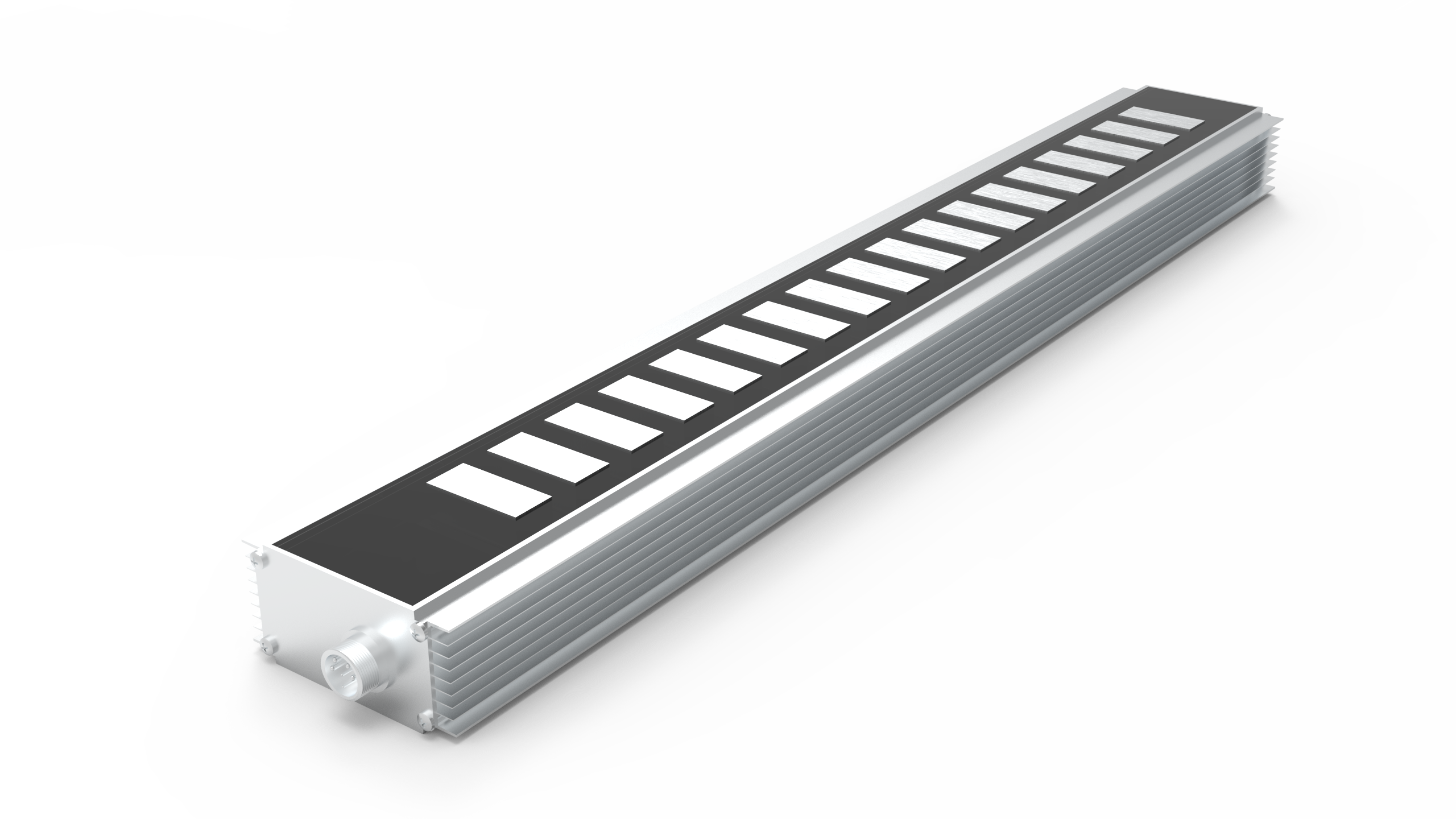
Engineers must match the motor architecture to the application. Three primary categories dominate the automation landscape today. They each handle physics differently.
First, consider ironcore models. The copper coils wind tightly around steel laminations. Manufacturers typically epoxy these coils into a robust block. This steel core concentrates the magnetic flux intensely. They are best for high continuous force. You use them for heavy payload transport. They excel in CNC machine tooling and metalworking. In these environments, cutting forces require massive resistance. Ironcore units push against these cutting forces effortlessly. Trade-offs certainly exist. The steel core creates massive attractive forces. It pulls downward toward the magnetic track constantly. Sometimes this downward force exceeds the actual payload weight. You need heavily over-engineered linear bearings. These bearings must support this extreme downward pull. Cogging forces are also present. The iron teeth prefer aligning with the permanent magnets. This magnetic preference causes slight motion ripples at low speeds. Controllers must work hard to smooth this out.
Next, we evaluate ironless models. They use a U-channel design. The coil assembly contains absolutely no iron. Manufacturers use epoxy to encapsulate the bare copper windings. It moves smoothly through a U-shaped magnet track. The track contains opposing magnets on both sides. They are best for ultra-high precision. You see them heavily in high-speed pick-and-place tasks. Semiconductor manufacturing relies on them exclusively for wafer scanning. Trade-offs include a lower moving mass. They exhibit zero cogging because no iron exists to attract the magnets. This makes them perfectly smooth at any speed. However, they output lower overall force than ironcore models. Heat dissipation is much poorer. No iron core exists to absorb and wick away the thermal load. If you push them too hard, the copper windings will overheat rapidly. You must monitor their duty cycle strictly.
Finally, we look at tubular or cylindrical designs. The design wraps the magnetic track into a enclosed cylinder. The forcer completely surrounds the stationary shaft. They look exactly like pneumatic air cylinders. They serve as excellent drop-in replacements. Engineers swap pneumatic cylinders for these electric alternatives to gain precise positional control. Cleanroom environments and food packaging lines use them extensively. You can wash them down easily. Trade-offs involve physical stroke limits. The enclosed design yields excellent IP ratings. It keeps out dust and water perfectly. Yet, it strictly limits maximum stroke lengths. The internal magnetic shaft lacks intermediate supports. It can sag if extended too far. This sag ruins the critical air gap and causes catastrophic scraping.
Automation Motor Architecture Comparison
| Architecture Type | Primary Advantage | Ideal Application | Main Drawback |
|---|---|---|---|
| Ironcore | High force density | Machine tooling, heavy transport | High attractive forces, cogging |
| Ironless (U-Channel) | Zero cogging, smooth motion | Semiconductor, optical alignment | Poor heat dissipation, lower force |
| Tubular / Cylindrical | High IP rating, enclosed | Pneumatic replacement, packaging | Strict stroke-length limitations |
Direct coupling transforms machine positioning capabilities entirely. Ironless models routinely achieve sub-micron positioning accuracy. They pair directly with high-resolution linear encoders. The encoder reads exact position data straight from the track. No mechanical compliance distorts the reading. The controller corrects motion errors instantaneously. You achieve absolute precision on every single pass. In optical inspection, this precision proves critical. Cameras must capture images without any jitter. The direct-drive system settles into position instantly. It does not oscillate or hunt for the target position.
Velocity and acceleration heavily influence machine cycle times. Traditional ball screws whip or vibrate at high speeds. Engineers call this the critical speed limit. This physical whipping destroys precision and damages components. You cannot run a long screw fast. Direct-drive units bypass this physical limit entirely. You can achieve velocities exceeding five meters per second easily. Accelerations frequently surpass 10G in light-payload applications. These extreme metrics drastically reduce index times between stations. Faster index cycles yield higher throughput. You manufacture more parts per hour. In mass production, saving fractions of a second equates to massive revenue gains.
We must contrast maintenance needs. Mechanical systems require constant lubrication schedules. Belts stretch under tension and screws wear out. Technicians must halt production to pump grease into bearings. Direct-drive technology removes these wearing parts completely. You eliminate complex maintenance schedules. The initial purchase price is undoubtedly higher. Advanced servo drives are mandatory. Rare-earth magnets cost significantly more than steel screws. However, avoiding constant part replacement maximizes machine uptime. The operational lifespan lengthens considerably. Facilities run continuously without mandatory mechanical rebuilds.
Cleanroom environments demand specialized motion solutions. Metal-on-metal friction generates microscopic particulates constantly. Ball screws shed grease and debris during operation. This contamination ruins semiconductor wafers. Direct-drive units operate entirely contact-free. The only moving contacts are the linear guides and cables. This clean operation proves vital for sensitive industries. Semiconductor, medical device, and optical manufacturing facilities rely on this cleanliness. They easily meet strict ISO cleanroom compliance standards. You do not need to enclose the mechanism in complex vacuum scavenging systems.
Heat generation poses a significant engineering challenge. The payload often mounts directly to the motor coil. Thermal energy transfers straight into the machine bed. This heat causes structural expansion. Precision degrades rapidly as machine components warp. Ironless models suffer most from this thermal buildup. High-duty applications require aggressive cooling strategies. Engineers frequently integrate water-cooling plates. We pump chilled fluid directly through the motor block. This prevents catastrophic precision loss. You must account for plumbing routing during the design phase. Fluid leaks can destroy the surrounding electronics.
Safety remains paramount during assembly. Ironcore units generate extreme downward magnetic pull. Safety protocols during assembly are absolutely critical. Technicians risk severe crush injuries. Unsecured components can snap together instantly. You must use specialized jigs to lower the coil onto the track safely. Furthermore, guideways must handle this massive pre-load. You must specify over-engineered linear bearings. Ordinary bearing rails will fail prematurely. The constant magnetic attraction crushes standard ball bearings. You must size mechanical guides for the magnetic load, not just the payload weight. This increases the overall system mass and cost.
The forcer moves rapidly across the track. It drags power and encoder cables closely behind it. Cable management becomes a primary failure point. Routing continuous-flex cables demands precision engineering. High speeds and massive accelerations strain protective jackets. The copper cores bend violently during operation. Poorly designed cable tracks cause premature wire fatigue. Engineers must optimize bend radii meticulously. You must use high-flex cables rated for millions of cycles. You must also separate power cables from signal cables. High-voltage power lines can induce electrical noise into the sensitive encoder signals.
Most direct-drive tracks remain completely exposed. In metalworking environments, this presents a severe risk. Strong permanent magnets attract ferrous debris instantly. Metal chips bridge the critical air gap. This causes catastrophic mechanical binding and sparks. You must install protective covers immediately. Bellows and wipers become necessary safeguards. Dirty environments demand fully enclosed tubular models or sealed tracks. Even non-magnetic dust can accumulate over time. It mixes with the bearing grease and creates an abrasive paste. Regular cleaning protocols remain essential even for contact-free motors.
Deciding on a motion technology requires analyzing core constraints. Not every machine needs direct-drive capabilities. Let us look at specific application triggers.
Direct-drive solutions do not universally replace traditional actuators. They stand as highly specialized tools. They conquer extreme speed, precision, and reliability bottlenecks. Their structural simplicity belies significant engineering and integration demands. Upgrading requires careful thermal and structural planning.
A: The primary cost drivers are the materials and supporting electronics. They require long tracks lined with expensive rare-earth magnets. Achieving sub-micron precision also necessitates high-resolution linear encoders. These encoders add significant cost. Furthermore, complex servo drives are required to manage the massive electrical currents rapidly.
A: Cogging refers to the magnetic attraction variance. It occurs as the iron coil moves over individual permanent magnets in the track. This creates a bumpy feeling at low speeds. Advanced controllers mitigate this by mapping the specific force ripples and applying counteracting electrical currents.
A: Yes, but they require additional hardware. Unlike ball screws, direct-drive units lack mechanical friction to hold a load when power drops. You must install physical counterbalances, magnetic springs, or pneumatic cylinders. These mechanisms prevent the payload from crashing downward during a sudden power loss.
A: Because they operate via magnetic fields across an air gap, there is zero internal mechanical contact. The only wearable components are the external linear guides and the flex cables. If you manage heat effectively and prevent cable fatigue, the coils and magnets boast a lifespan spanning decades.


 English